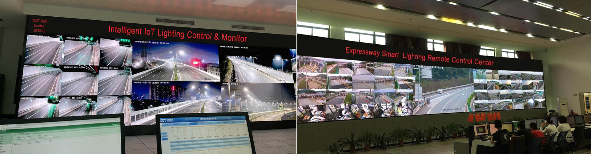
See every light on a Google Maps-based view. Receive power consumption reports and fault alarms. Send linked work orders by email or SMS to the right maintenance crew and verify closure. The city moves from complaint-led repairs to measured, accountable lighting operations.
STSYSTEMPLC links Grid → Cabinet → Circuit → Lamp through CH-800, HYBRID PLC & LoRA, sensing and an IoT Lighting Platform. Energy savings depend on the existing HPS system, the approved dimming schedule and actual traffic. Suitable projects may also target a 50–70% reduction in maintenance costs, verified against the owner’s baseline.
93km Shenzhen Outer Ring Expressway Smart Lighting: a full-width engineering reference for long-corridor roadway and tunnel lighting. This is 100% real on-site footage filmed by our team, not a simulation or stock scene. Two high-speed trains traveling at 350 km/h each cross beside a dense 800 kV ultra-high-voltage network along the corridor. In this demanding infrastructure environment, the STSYSTEMPLC HYBRID PLC & LoRA lighting system operated normally.
Interconnected smart roadway, street and tunnel lighting links the power grid, cabinets, circuits, luminaires, sensors, CH-800 local control, HYBRID PLC & LoRA field communication and an IoT Lighting Platform. It applies approved scenes, reports energy and faults, maps assets, routes maintenance work and maintains approved local operation when external connectivity is lost. An HPS retrofit must be judged against the owner’s measured energy and maintenance baseline.
Four Results Owners Can Verify
See the affected pole on a permitted Google Maps-based or local GIS view; receive energy reports and alarms; assign an email/SMS-linked work order and verify restoration.
80–92% energy and 50–70% maintenance reductions are targets for qualifying HPS projects. Compare like-for-like kWh, visits, materials and service periods after commissioning.
CH-800 applies approved local rules while controllers, sensors, HYBRID PLC & LoRA and the platform link lighting operation to the owner’s records.
The 93km Shenzhen Outer Ring Expressway video above is real site footage. The 55km bridge crossing, Shenzhen–Zhongshan Link with an 8-lane undersea tunnel and investment near USD 6.7 billion, and the 177km / approximately 28,000 terminals reference show distinct infrastructure duties; restricted operating files remain with their owners.
A smart lighting project becomes credible when the road is divided by real operating conditions: straight sections, bends, slopes, junctions, tunnel portals, fog-prone valleys, power-feeder boundaries, communication shadows and maintenance access. A simple pole-by-pole copy of the same sensor and dimming rule is not enough for highways, bridges, tunnels or mountain roads.
The same engineering logic used for demanding roadway and corridor projects applies here: define the users and vehicles the system must serve, test the actual approach directions, hold the occupied scene during continuous traffic, suppress nuisance triggers and record the accepted rule set for the owner.
| Corridor Condition | Lighting-Control Risk | STSYSTEMPLC Design Response |
|---|---|---|
| Bends, slopes and hidden approaches | A vehicle can reach the next road section before a distant sensor detects it. | Position sensors and advance lighting zones according to actual sightlines, with overlap where terrain or structures hide the approach. |
| Tunnel entrance and exit areas | Daylight adaptation, fog, glare and incident priority can conflict with ordinary energy-saving rules. | Give portal zones their own scene hierarchy, luminance/weather inputs, manual override and FAT/SAT evidence. |
| Continuous traffic or convoy movement | Lights should not repeatedly rise and fall every few seconds. | Refresh the occupied scene and hold the approved output until the traffic condition clears. |
| Wind, rain, animals, vegetation or adjacent-road movement | Nuisance triggers can waste energy and damage owner confidence. | Narrow the detection area, tune sensitivity, separate adjacent traffic and document both missed detections and unwanted triggers. |
| Remote, high-risk or weak-grid sections | Cloud loss or communication interruption must not leave the road without approved local control. | Store approved scenes in CH-800 / local controllers, test fallback and recover event records after reconnection. |
Replacing HPS with LED reduces the power consumed by the luminaires when the new photometric design is accepted. The operating case adds fault visibility, controllable scenes, energy records and accountable repairs. The EPC must price the reused pole, cabinet, feeder and tariff boundary as carefully as the new luminaire.
| Owner Pain Point | Operational Consequence | STSYSTEMPLC System Answer |
|---|---|---|
| HPS lamp, ballast or circuit fault found late | Complaints or patrols discover darkness; a crew still has to locate the electrical cause. | Map pole → controller → circuit → cabinet, classify the alarm and record verified repair. |
| HPS energy and relamping burden | Power, lamp/ballast replacement and night access remain separate recurring cost lines. | Compare accepted HPS baseline with complete LED luminaire watts, scene hours, maintenance visits and metered results. |
| LED-only upgrade without operations data | Lower watts do not by themselves locate a failed pole, verify a scene or close a work order. | Connect supplied controllers, CH-800 rules and IoT Lighting Platform to the owner’s asset and event records. |
| Unknown outage location | A complaint or patrol finds the problem before the control room. | Map each asset and classify power, controller and communication alarms. |
| Uniform nightly output | Energy is spent without regard to schedule or approved traffic conditions. | Use tested dimming scenes with minimum photometric requirements. |
| Disconnected electrical records | The platform cannot explain a circuit-level bill or outage. | Link Grid → Cabinet → Circuit → Lamp identities and meter boundaries. |
| A single fragile field channel | Cable noise or RF obstruction leaves devices unreachable. | Survey PLC and LoRA paths and verify two-way fault transfer. |
| A cloud-only rule | External-network loss interrupts supervision or control. | Run agreed scene and schedule logic locally through CH-800. |
| A dashboard without closure | Faults remain open after a visit. | Connect alarm → dispatch → repair → retest → closure. |
| Vendor-dependent handover | The new operator lacks accounts, maps and recovery files. | Transfer permissions, exports, configuration and restore procedure. |
A city can keep an HPS network temporarily, replace luminaires with LED, or connect the new lighting into an operating system. Compare the same road classes and service area in all three cases. The connection decision affects fault response, scene control and the owner’s future operating costs; estimate these costs separately from the luminaire purchase price.
| Owner Decision | Retain Conventional HPS | LED-Only Replacement | STSYSTEMPLC Interconnected Upgrade |
|---|---|---|---|
| Energy | Use the actual lamp-plus-ballast input and billed hours. | Lower luminaire input where the accepted design permits; fixed schedules may remain. | Measure installed LED input plus controller load, then log approved scene hours and exceptions. |
| Fault discovery | Often depends on patrols, calls or cabinet-level observation. | Longer-life luminaire, but individual failure visibility depends on supplied controls. | Link the pole, controller, circuit and cabinet alarm to a repair action and verified closure. |
| Night scenes | Commonly a fixed switching plan, subject to existing equipment. | Driver may support a schedule; owner feedback varies by design. | CH-800 local rules coordinate approved schedules, traffic and weather scenes by zone. |
| Retrofit exposure | Recurring lamp and ballast service continues. | Survey pole, mounting, optics, wiring and tariff before replacing. | Survey the same electrical assets plus driver interfaces, controller power and network coverage; phase by zone. |
| Owner handover | Maps and maintenance records may be fragmented. | A new equipment register can still remain separate from operations. | Deliver a reconciled asset register, role-controlled platform, scene file, backup and maintenance workflow. |
The committee signs for a public service that must keep working through weather, outages, budget cycles and contractor changes. It needs a compact decision case before evaluating controller details.
A city buying 10,000 lights should be able to answer three questions in one meeting: what must work on day one, what recurring cost is being accepted, and how will the city know whether the promised service was actually delivered? The lighting design, network design and software contract must all support the same answer.
Organize the proposal around one responsibility chain. The owner defines photometric classes and operating policy; the EPC builds the electrical and communications system; the technology supplier provides device functions and integration evidence; the maintenance contractor closes alarms against the physical asset. Every unassigned interface becomes a future outage or variation order.
At approval stage, ask for a representative zone costed in the same way as the full city. A single-lamp price excludes trenching, cabinet work, subscriptions, SIM traffic, batteries, configuration, site tests and long-term spare parts. The committee needs those lines visible before it compares bids.
| Committee Decision | Question That Exposes the Risk | Reviewable Deliverable |
|---|---|---|
| Service objective | Which streets and tunnels have priority, and what happens during an incident? | Approved lighting classes, scenes and exception priority. |
| Capital scope | Are existing drivers, poles, cabinets and ducts reused or replaced? | Survey, interface list and priced bill of quantities. |
| Recurring cost | Who pays for network, hosting, SIMs, energy and software support? | 10-year operating-cost schedule and contract boundary. |
| Delivery risk | Which party owns sensor, CH-800, controller and platform integration? | Signed interface responsibility matrix. |
| Owner control | Can the city export maps, logs, settings and accounts? | Data rights, backup and restore demonstration. |
| Performance acceptance | Which conditions make a payment milestone pass or fail? | FAT/SAT criteria tied to actual installed assets. |
| Maintenance value | How quickly can a dark asset be found, repaired and closed? | Alarm classification, work-order process and service KPIs. |
The committee should not receive only one oversized system package. Present three buildable scopes against the same accepted operating duties so that price differences have an intelligible cause.
A retrofit can retain sound poles, cabinets and luminaires while adding control and monitoring at the available driver interface. Its main risk is inherited wiring, incomplete records and inconsistent equipment ages. An EPC should price the survey and interface exceptions rather than assume every existing luminaire can accept the same node.
A phased upgrade replaces selected high-fault or high-energy zones first and builds the asset map, CH-800 gateway plan and control-room workflow before expanding. The owner can learn from a representative city street, highway segment and tunnel portal, but the phases must share address rules, data fields and handover standards. Otherwise the next phase creates a separate, incompatible system.
A full reconstruction can unify optics, cabinets, power, sensors and communications, but it carries the largest civil-work and program risk. The comparison must include traffic management, trench reinstatement, project management, software service and testing. The committee should ask whether the extra capital buys a measurable operating obligation that a retrofit cannot meet.
All three options can be judged by the same scorecard: accepted photometrics, command success, asset visibility, fault-to-closure time, energy measurement, offline continuity, owner data rights and lifecycle cost. The price should be shown per light, per cabinet, per km where meaningful, and for the whole owner portfolio.
| Investment Route | What It Reuses | Principal Risk | Decision Gate |
|---|---|---|---|
| Control retrofit | Existing power, poles and suitable drivers. | Legacy interface and undocumented feeder constraints. | Survey sample and model compatibility test. |
| Phased upgrade | Usable portions of the existing network. | Incompatible phases and duplicated platforms. | Common asset schema and expansion plan. |
| Full reconstruction | Only the site corridor and approved area for civil works. | Capex, trenching and disruption. | Whole-life cost and program-risk review. |
| Hybrid by zone | Retain sound urban assets; rebuild high-risk segments. | Complex responsibility boundary. | Zone-by-zone bill and one owner control model. |
For the business committee, “pilot” should mean a representative zone with a defined budget and measurement equipment, not a showroom installation. A useful sample includes a sound HPS feeder, a difficult cabinet, a fault-prone section and, when in scope, a tunnel portal. The EPC records exceptions and uses them to update the full bill of quantities.
| Program Gate | What the Owner Learns | Release Evidence |
|---|---|---|
| 1. Survey and baseline | Actual HPS lamp-plus-ballast power, tariffs, fault history, pole and cabinet condition. | Inventory, meter boundary, photometric class and interface exceptions. |
| 2. Representative zone | Whether the offered luminaire, driver, controller, CH-800 and platform work together. | Night measurements, scene tests, fault ticket and restored local rule. |
| 3. Staged districts | Real installation rate, crew access, communications coverage and unit cost. | Zone sign-off, asset reconciliation and a revised delivery forecast. |
| 4. Citywide operation | Whether savings and service continue after the EPC leaves. | Owner-controlled accounts, performance reports, spares and maintenance contract. |
An interconnected smart lighting system links the grid, cabinets, circuits, lamps, sensors and IoT Lighting Platform into one monitored operating chain. The city must be able to trace a command to the physical light, verify feedback, identify a failed layer and keep approved local scenes active when external connectivity is interrupted.
| Layer | Owner-Controlled Scope | What Can Go Wrong | Required System Response |
|---|---|---|---|
| Grid | Supply origin, backup policy and outage boundary. | Power failure is mistaken for a communication fault. | Show supply status and the exact assets affected. |
| Cabinet | Feeder switching, protection and manual authority. | Crews search the wrong cabinet or circuit. | Keep a cabinet-to-circuit asset map and isolation record. |
| Circuit | Road section, meter boundary and distribution route. | Energy and outage reports have no electrical basis. | Reconcile meter readings, connected loads and zone state. |
| Lamp | Luminaire, driver, controller and pole identity. | A command appears sent while the lamp remains dark. | Record supported feedback, exception and work order. |
| CH-800 + Platform | Local rules plus fleetwide oversight. | Cloud loss disables an approved scene. | Continue configured local behavior and sync records after recovery. |
Start with one pole and trace it upward to its circuit, cabinet, gateway zone and owner account. Then start with an outage and trace it downward to the exact field device and repair action.
| Owner Value | What Changes Operationally | How It Becomes Measurable |
|---|---|---|
| Energy accountability | Power consumption reports show lamp, circuit and zone behavior against the approved scene plan. | Reconcile meter boundary, scene hours and bills against the HPS baseline. |
| Earlier fault response | Map-linked alarms identify the physical pole and likely electrical or communication boundary. | Measure fault-to-awareness and fault-to-restoration by road priority. |
| Less blind fieldwork | email/SMS routing gives the crew an asset ID, location, fault type and linked work order. | Compare patrol rounds, unnecessary visits and first-visit resolution. |
| Safer scene governance | Road, tunnel and weather scenes remain within approved local rules and operating authority. | Retain scene history, override reason and site acceptance result. |
| Owner control after EPC handover | Asset identities, settings, permissions and repair records remain usable when crews change. | Prove export, backup, role change and restoration on supplied hardware. |
Smart-city value is concrete during a night shift. The operator receives a complaint, outage, flood warning, work permit or abnormal energy reading and must decide what to do without searching several disconnected systems.
The first screen should show a trusted asset identity and the last reported electrical and communication states. A pole location alone is insufficient: the operator needs its cabinet, circuit, controller, active scene and neighboring lights to decide whether the response belongs to the electrician, the communications team or the traffic-control room.
Nighttime operations also expose false confidence. A platform can report the last command as “ON” while a breaker has tripped. The system therefore distinguishes command issued, command received, available controller feedback and measured electrical power. Those are separate observations with different uncertainty.
Where a municipality already owns a complaint or work-order system, define the integration fields at tender stage: asset ID, fault type, priority, assigned team, work-order number, action, test result and closure time. A beautiful dashboard without this loop leaves the same crews making the same trips.
| Control-Room Call | Immediate Information Needed | Owner Action and Record |
|---|---|---|
| “This road is dark.” | Cabinet supply, circuit, lamp/controller and last-seen state. | Open the correct incident and dispatch to the right boundary. |
| “The tunnel portal is too bright.” | Luminance input, current scene, daylight level and override. | Review sensor and rule before changing output. |
| “Fog is entering the mountain road.” | Weather source, threshold, CCT state and affected zone. | Approve or verify the weather scene and observe recovery. |
| “This area used too much energy.” | Meter boundary, scene hours, standby loads and exceptions. | Recalculate against the accepted baseline. |
| “The contractor says it is fixed.” | Before/after device status, repair note and retest. | Close only after verified restoration. |
The EPC contractor is responsible for turning separate lighting, power, sensing, controls and software scopes into one operating installation. Interfaces must be frozen before procurement and tested before trenching, commissioning and handover are treated as complete.
A roadway package often divides across civil works, poles, cables, cabinets, luminaires, controllers, gateways, communications and software. Each supplier may pass its factory test while the site system still fails. The EPC should own the integrated drawings and command chain, with each product supplier providing model-specific wiring, protocol fields, environmental ratings and service procedures.
For tunnels, coordinate lighting with the electrical distribution and the approved safety or traffic systems. Define exactly which inputs can invoke a priority lighting scene, who has manual authority and what happens on lost input. The EPC should not assume that a network path, battery, panel breaker or controller has been included because another package lists a related function.
Make the interface register a live commissioning document. Record each signal source, connector, controller model, field address, message field, power source, cabinet, target scene, acceptance method and responsible person. After one representative zone passes SAT, use the signed configuration baseline for the remaining zones.
| EPC Package Boundary | Common Gap | Document and Test to Close It |
|---|---|---|
| Power ↔ controls | Controller and gateway lose power while the lamp remains on or off. | Power tree, standby consumption and outage test. |
| Driver ↔ controller | Dimming interface or feedback is incompatible. | Exact driver model, wiring, function list and mock-up test. |
| Sensor ↔ CH-800 | Input does not map to the intended zone or priority. | I/O schedule, event fields and scenario test. |
| CH-800 ↔ platform | Local and central rule versions differ. | Configuration version, authority and sync test. |
| PLC ↔ feeder | Transformer boundary or line noise breaks communication. | Feeder survey, PLC signal measurement and alternatives. |
| LoRA ↔ gateway | RF shadow, licensing or gateway position is overlooked. | Coverage survey, antenna plan and field-channel test. |
| Commissioning ↔ maintenance | Field addresses, spares or backups are missing. | As-built map, restore file and owner training. |
A procurement specification is still incomplete if the field team cannot install, address and test the equipment without guessing. The EPC design package should be reviewable before cabinets are fabricated or sensors fixed to poles.
The photometric package defines road classes, tunnel scenes, optic selections, maintained calculations, glare criteria and the accepted dimming minimum. The electrical package defines source, cabinet, feeder, circuit, protection, earthing and backup. The controls package defines every pole ID, controller, gateway, sensor, communication route, local scene and platform field. These drawings must reference the same asset identifiers.
For communications, show PLC feeder boundaries and expected noise sources on one drawing, and LoRA gateways, antennas, heights, RF survey points and intended overlap on another. The control sequence should say whether PLC is primary, LoRA is primary or the logic varies by zone. Name what happens when one path is degraded but not fully lost.
For software, deliver the data dictionary and roles before commissioning. The platform must not label “actual watts” if the installed device only reports a calculated estimate. The integration schedule should distinguish a requested dimming level, acknowledged command, measured power, controller alarm and cabinet-level meter. Each field needs a source, unit, interval and stale-data rule.
For site works, align location and access with traffic management, maintenance vehicle approach, tunnel closures and night shift staffing. Testing a sensor at a quiet factory bench does not establish reliable behavior after it is mounted above a multi-lane road. The EPC owns the installed geometry and the signed exceptions list.
| Preconstruction File | Contents | Review Owner |
|---|---|---|
| Photometric design | Road/tunnel classes, optics, scene levels, maintenance factors and drawings. | Lighting consultant and owner operations. |
| Single-line electrical | Grid, cabinet, circuit, protection, battery and charging boundary. | Electrical designer and asset owner. |
| Control sequence | Inputs, rule priority, outputs, delay, fallback and override. | System integrator and owner control room. |
| PLC / LoRA survey | Conductor and RF topology, shadowing, gateway placement. | EPC communications engineer. |
| Point schedule | Pole, lamp, driver, controller, gateway, sensor, meter and platform tag. | EPC commissioning lead. |
| Data dictionary | Units, source, interval, measured/estimated status and export. | Owner IT and maintenance. |
| Test scripts | FAT, site mock-up, SAT, failure injection and punch-list process. | Independent witness and owner. |
City streets, high-speed roads and tunnels can use the same control and monitoring architecture while retaining distinct photometric rules and operating priorities.
Manage pole-level faults, cabinet circuits, schedules, authorized dimming, energy and citizen-service maintenance.
Coordinate long zones, traffic-sensing inputs, communication continuity and advance lighting where the project design requires it.
Control entrance, threshold, transition, interior and exit scenes with luminance inputs, emergency priorities and local fallback.
| Duty | Design Input | Control and Monitoring Evidence |
|---|---|---|
| City street | Pole inventory, road classification, cabinet and circuit map. | Single-lamp command, fault location, power records and dispatch closure. |
| Expressway | Speed class, pole spacing, sensor location and long-corridor topology. | Zone timing, status continuity, energy profile and field-channel health. |
| Tunnel | Portal luminance, daytime change, traffic and emergency interface. | Scene curve, priority override, luminance feedback and local operation. |
A tunnel is not a covered street. Drivers arrive from changing daylight, pass threshold and transition zones, enter the interior and exit into another daylight condition. The control plan must manage the Black Tunnel and White Tunnel Syndrome (black-hole and white-hole effects) within the approved tunnel photometric design.
At the entrance, portal luminance and approach conditions influence the threshold scene. In the interior, continuity, uniformity and emergency visibility matter. At the exit, transitions must avoid a sudden mismatch. STSYSTEMPLC CH-800 rules can organize approved zone scenes, but the photometric design and local authority requirements define the actual outputs.
The commissioning sequence should include bright daylight, overcast change, night mode, sensor failure, one controller fault, communication interruption and an authorized incident override. For each condition, record the source input, rule priority, command, measured light and return to normal operation. A single sunny-day demonstration is inadequate for a tunnel handed over for continuous public use.
National tunnel operators may require closed networks, locally retained rules and restricted access to operating data. Design the interface boundary around the owner’s security and life-safety policy; do not infer that a cloud dashboard has authority over emergency behavior.
| Tunnel Zone | Engineering Decision | FAT/SAT Evidence |
|---|---|---|
| Approach and entrance | Map outside luminance to the accepted threshold scene. | Sensor validation, command trace and luminance measurement. |
| Threshold | Control the daylight-to-tunnel adaptation. | Zone output, uniformity, glare and stable transitions. |
| Transition | Reduce output according to the approved curve. | Scene sequence and change-rate test. |
| Interior | Provide the required base and priority scenes. | Night/day measurements and local fallback. |
| Exit | Coordinate internal-to-external visual conditions. | Exit measurement and abnormal-input test. |
| Incident or emergency | Enforce owner-approved priority, not an unreviewed algorithm. | Manual authority, precedence and recovery record. |
Tunnel modernization must fit lane-closure windows, access restrictions and the owner’s incident procedures. Before any cutover, the EPC maps the old and new circuits, labels temporary supplies and defines the moment at which the control room accepts the new scene authority. One failed sensor or gateway must not leave the portal without its approved fallback.
| Cutover Step | Operating Constraint | Owner Sign-Off |
|---|---|---|
| Survey and mock-up | Measure entry luminance, existing circuits, mounting and access. | Approved design, phasing and temporary lighting plan. |
| Install by closure zone | Separate traffic management, power isolation and installation crews. | As-built zone map and electrical test. |
| Scene and fault test | Exercise daylight change, night, lost sensor, lost link and manual priority. | Photometry, fallback behavior and operator procedure. |
| Control-room handover | Return traffic only under the accepted operating mode. | Signed scene file, alarm route, training and recovery ownership. |
PLC can use suitable power conductors; LoRA gives an independent wireless route. Old-city poles, mixed feeders, electrical noise, terrain and tunnel geometry each change the quality of those routes.
The 93km Shenzhen Outer Ring Expressway footage was recorded on site. It shows two trains traveling at 350 km/h each crossing beside the corridor’s dense 800 kV ultra-high-voltage network. The STSYSTEMPLC HYBRID PLC & LoRA system operated normally in this project environment. The footage shows the actual infrastructure setting; the normal operation statement reflects STSYSTEMPLC’s experience on this project.
| Communication Condition | PLC Route | LoRA Route | HYBRID PLC & LoRA Acceptance |
|---|---|---|---|
| Normal operation | Use a surveyed feeder topology and validated signal quality. | Use surveyed RF coverage and gateway placement. | Record command and status delivery on each path. |
| Conductor noise or PLC interruption | Affected path may fail or degrade. | Independent RF path can continue if devices remain powered. | Measure PLC → LoRA takeover to the specified 0.1 s target. |
| LoRA interference or lost RF coverage | Healthy conductor path remains available. | Affected path may fail or degrade. | Measure LoRA → PLC takeover to the specified 0.1 s target. |
| Power failure | A communication path cannot restore power to a dark lamp. | The alternate route also needs powered endpoints. | Separate power backup from data-path redundancy. |
| Complex legacy road | Transformers and third-party wiring may disrupt PLC. | Wireless coverage can bypass irregular conductor topology. | Select paths by zone after site survey and SAT. |
For a project at the scale of the 93km Shenzhen Outer Ring Expressway, a route drawing alone is not a control architecture. Divide the corridor by power source, cabinet, communication quality, tunnel/road interface, weather exposure and maintenance access.
Within that corridor, geometry matters. Curves, crests, cuttings, bridge approaches, tunnel portals, retaining walls, trees and mountain fog areas can hide an approaching vehicle from a repeated straight-road sensor layout. Place the sensing zone, lighting-response zone and warning zone around the actual sightline, not around a drawing-grid assumption.
Dense or continuous traffic also changes the control strategy. A high-speed road, tunnel approach or event traffic queue should refresh the occupied scene and hold the accepted output; it should not make a long row of lamps pulse up and down because each pole sees a separate event.
Each gateway zone should have an unambiguous asset count, upstream link, field-channel route, local rule set and failure behavior. Document how the operator can distinguish a dark lamp from a dark circuit, an unreachable gateway and a temporarily missing cloud connection. When many alarms arrive together, the platform should group them by probable common cause rather than send a crew to every pole.
Commission one representative segment containing normal road, complex power topology and a tunnel portal where the project has them. Complete both communication-channel interruption tests, the photometric acceptance and the owner backup/restore exercise there. Use its signed settings as a repeatable reference for staged deployment, while retaining the right to adjust RF coverage or PLC parameters after each site survey.
A corridor at the 93km Shenzhen Outer Ring Expressway scale requires coordinated control of light, power and communication across many operating zones. The on-site film shows the crossing of two 350 km/h trains and the 800 kV ultra-high-voltage network along the corridor. The HYBRID PLC & LoRA system operated normally in this setting.
| Corridor Design Layer | Question at Design Review | Evidence at Handover |
|---|---|---|
| Route partition | What is the electrical and operating boundary of each zone? | Zone drawings, cabinet/circuit map and installed pole count. |
| Gateway capacity | How many devices and rules does each CH-800 serve? | Capacity allocation, timing and fallback test. |
| Field communication | Where is PLC strong; where must LoRA carry the load? | Survey maps and both channel-quality records. |
| Backhaul | Where does platform connectivity end? | Link availability and local-record recovery test. |
| Maintenance access | How will crews reach the right fault at night? | Pole ID, cabinet ID, access plan and dispatch path. |
| Expansion | Can a new zone be added without corrupting existing settings? | Address scheme, configuration version and staged SAT. |
No single field network is the right default for every city pole, expressway feeder and remote island road. The communication choice should follow an electrical and RF survey and the required telemetry interval, response, recurring cost and local autonomy.
PLC is strongest when conductor topology is known and measured line quality is adequate. In old urban areas, one pole may share an electrical history with residential feeds, multiple transformer boundaries and crowded telecommunications cables; LoRA can be a practical route where PLC cannot be made reliable. HYBRID PLC & LoRA gives a configured alternative path, provided both radios and controllers retain power.
CAT-1 direct-to-cloud operation serves selected assets where a local gateway is impractical, where theft alarms must be sent during the day, or where a battery can maintain controller communication through grid interruption. NB-IoT/CAT-1 assignments must reflect carrier coverage, data plan, power budget and what the owner needs when cellular service fails.
Do not merge “0.1-second lighting response,” “0.1-second field-channel takeover” and “24-hour online monitoring” into one test. Each has different start and stop conditions, different devices and different evidence. The tender schedule should name each boundary and the models that can support it.
| Field Route | Best-Fit Condition | Failure to Design For | Project Evidence |
|---|---|---|---|
| PLC | Regular feeder with measured signal quality. | Noise, transformer crossing, supply interruption. | PLC survey and command/status log. |
| LoRA | RF coverage across difficult or mixed-power sites. | Shadowing, interference, gateway power. | RF survey and lost-link recovery. |
| HYBRID PLC & LoRA | The owner needs alternative field paths. | Unpowered endpoint or simultaneous path loss. | Two-direction takeover and recovery. |
| CAT-1 | Selected direct SIM-equipped asset or remote group. | Cellular loss, subscription, standby drain. | Signal and 24-hour power test where supplied. |
| NB-IoT | Selected low-data telemetry where carrier support fits. | Latency, coverage and lifecycle. | Device/plan match and site polling record. |
CH-800 is the local decision point; the platform is the owner’s portfolio view. A system should still behave sensibly when the cloud cannot see it.
| Function | Local CH-800 Responsibility | Platform and Owner Responsibility |
|---|---|---|
| Schedules and priorities | Store the approved rule and apply it within the commissioned zone. | Approve the rule, permissions, version and reporting period. |
| Field data | Receive available controller and sensor messages. | Show asset state, exceptions, alarms and trends. |
| Network interruption | Continue the agreed local scene and retain supported events. | Show gap and recovery after synchronization. |
| Maintenance | Keep physical device and zone identity consistent. | Assign work, verify repair, record part and close alarm. |
| Configuration changes | Execute the authorized version within scope. | Audit who changed what and restore the accepted backup. |
Deployment can be cloud or on-premises. Define data ownership, user roles, retention, export, backup, cybersecurity responsibilities and software support in the project schedule.
An IoT Lighting Platform can be cloud-based or deployed on-premises. The owner’s data policy, network rules, operating staff and maintenance contract decide which model is suitable for each project.
From an owner’s perspective, “access” is not one password. Define viewing rights, command rights, emergency override, configuration editing, export, firmware management and account recovery. Name the operator or department that grants each permission and retains the audit trail. For an EPC, these rules become a test schedule and handover file rather than a late software preference.
Data quality also needs governance. A lamp status is meaningful only when it has the correct pole and timestamp; an energy total is meaningful only with a declared meter boundary; an alarm is useful only when its location and action status are clear. The platform should show unknown or stale data honestly, not paint it as current.
Software maintenance belongs in the lifecycle budget. Identify the supported update mechanism, configuration backup, version comparison, retention and restore procedure for the supplied gateway and controllers. Test a restoration on representative installed hardware before contractor handover.
| Governance Decision | Owner Requirement | EPC / Supplier Deliverable |
|---|---|---|
| Cloud or on-premises | Location of data and operating authority. | Network diagram and deployment boundary. |
| Accounts | View, operate, approve, configure and administer separately. | Role matrix and access test. |
| Data retention | Keep alarms, energy and event history for the agreed period. | Storage policy and owner export. |
| Third-party interface | Define exactly what can read or command assets. | Field list, authentication and interface test. |
| Restore | Operate after lost gateway or software configuration. | Backup set and practical restore result. |
Interconnected means more than devices sharing a dashboard. The EPC must define the interface between lamp controllers, CH-800, IoT Lighting Platform, the owner’s GIS or asset register, complaint system and work-order system. Existing third-party luminaires can be evaluated by their actual driver and controller interfaces rather than assumed compatible by name.
| Interface | Contract Question | Acceptance Exercise |
|---|---|---|
| Asset identity | Which pole, luminaire, controller, cabinet and circuit IDs remain stable across systems? | Reconcile a field sample against GIS and platform records. |
| Events and status | Which values are measured, inferred, stale or unavailable, and with what timestamp? | Create a real fault and compare each system’s event fields. |
| Command authority | Who can schedule, dim, override and restore a scene, with which priority? | Test role permissions and competing commands on a representative zone. |
| Maintenance exchange | How do alarm ID, work-order ID, repair note and retest result travel? | Close one ticket end to end, including a reopened fault. |
| Supplier exit | Can the owner export inventory, scenes, history and configuration? | Export, rebuild a test environment and verify access after handover. |
In connected deployments where Google Maps services are permitted, the platform can use a Google Maps-based view for pole location and operational status. A closed-network deployment uses the owner-approved local map or GIS layer instead. Map pins must be tied to installed asset IDs rather than treated as proof of lamp operation.
When a supported controller reports a fault, the platform records the source, time, severity and affected cabinet/circuit. Configured email or SMS notifications carry the asset location and a linked work-order ID to the authorized crew; the maintenance workflow records acknowledgment, action, retest and closure. Suppression rules prevent one feeder outage from generating thousands of unrelated crew trips. Power consumption reports state the meter boundary, period, scene hours and missing-data intervals.
Some roads have weak or irregular grid service, theft risk or isolated pole groups. A selected CAT-1 single-lamp controller can communicate directly through its internal SIM without depending on a nearby field gateway.
For 24-hour monitoring, the supply design must keep the controller energized while the luminaire is off. Where a street-light battery provides that standby power, confirm the energy budget, coverage, alarm latency and what happens during a long grid outage. Optional GPS location reporting belongs to the selected model and integration scope.
| Project Condition | Control / Monitoring Need | Site Test |
|---|---|---|
| Remote road asset | Direct cloud communication without a local gateway. | SIM coverage, data plan, message interval and recovery. |
| Weak or intermittent mobile signal | Retain useful event data during a short interruption. | Outage, retry and buffered-report behavior of the supplied model. |
| High theft exposure | Receive a defined removal or abnormal-energization event. | Trigger condition, owner notification and closure record. |
| Luminaire off by day | Keep controller power if 24-hour monitoring is required. | Battery or auxiliary supply budget and actual operating duration. |
A weather sensor should change an approved lighting scene, not just decorate a dashboard. BANYIN Freeway shows the sensor inputs to a network that can respond to rain, fog, snow, low cloud or other specified conditions.
Each condition needs its own sensor source, threshold, validity check, delay, scene priority, output and recovery rule. The city should see which input caused a change and whether the installed lamps actually executed it.
BANYIN Freeway Weather Sensing Network: Weather-related field sensing reference. Use the video to discuss how validated sensor inputs select CH-800 zone scenes; the acceptance test must identify the installed sensor, threshold, output, record and fallback.
| Weather Input | Possible Lighting Decision | Monitoring and Recovery |
|---|---|---|
| Heavy rain | Apply the approved road brightness or caution scene. | Validate input and retain output and power records. |
| Mountain fog | Compare normal and weather scenes with actual optic and visibility criteria. | Record scene, sensor health and return threshold. |
| Snow or frost | Use the approved warm CCT option where dual-CCT hardware is installed. | Measure CCT, maintained light and stable switching. |
| Sensor failure | Do not allow an unknown reading to reduce lighting unsafely. | Use the accepted local scene and raise a maintenance alarm. |
A weather network changes lighting only when a measured input, threshold and approved output are connected. BANYIN Freeway makes that input-to-scene control relationship visible across mountain, coastal, urban and highway environments.
In mountain fog, the weather source may be visibility or a validated combination of humidity, temperature and local observation; humidity alone should not be treated as visibility. In snow, reflected glare and the selected optical distribution matter. In rain and sea mist, surface reflections can change the useful light pattern. In wind-blown dust, the sensor may be less reliable, so the design needs a fallback and operator authority.
An EPC needs a weather input schedule listing sensor ID, location, calibration, refresh interval, confidence, trigger threshold, delay or hysteresis, zone mapping, scene priority, fault state and return condition. Site acceptance should replay changing and conflicting inputs, including a failed sensor, instead of only proving that one manual button changes color temperature.
The city committee needs the budget boundary: is weather adaptation supplied on every road, on selected high-risk mountain or coastal segments, or only at tunnel portals? Different choices drive sensor quantity, cabling, maintenance and the expected benefit.
| Weather Case | Wrong Shortcut | Reviewable Scene Logic |
|---|---|---|
| Mountain fog | Switch from humidity alone. | Use validated visibility/approved input, delay and site assessment. |
| Snowfall | Assume warm CCT always increases visibility. | Compare output, glare and contrast with both CCT states. |
| Sea mist | Ignore wet-surface reflections. | Use site photometric review and a stable trigger. |
| Heavy rain | Overreact to a brief sensor pulse. | Apply threshold, persistence and recovery rule. |
| Dust storm | Assume the sensor remains fully reliable. | Define fault flag, safe scene and manual authority. |
| Rapid weather change | Allow scenes to oscillate. | Set hysteresis, hold time and priority with event logs. |
In snowy cold regions and fog-prone mountains, a 2700K warm-light scene can be selected alongside the normal 6000K scene. The purpose is an operating option for the supplied optics and site conditions; CCT alone does not establish a universal visibility advantage.
Use weather sensors and CH-800 rules to define exactly when the scene changes, how long it remains active and how it returns. Test actual CCT, light output, uniformity, glare and power in both states.
Dual CCT Weather Adaptive Lighting: 6000K → 2700K scene demonstration. Confirm the supplied dual-CCT luminaire, weather input, threshold, delay, operator override, measured output and fault recovery.
| Environment | Scene Question | FAT/SAT Evidence |
|---|---|---|
| Snow and white surroundings | Does the warm scene help the approved design retain useful contrast without excess glare? | Comparative measured photometrics in the selected luminaires. |
| Dense mountain fog | Which sensor input and threshold select the weather scene? | Trigger trace, CCT, output, hold time and recovery. |
| Sea mist or wind-blown dust | Is a warm option useful for this site and optic? | Side-by-side field review under representative conditions. |
| Unreliable weather input | Which local scene takes precedence? | Fault alarm, safe fallback and return to automatic. |
Dedicated guidance and warning lights alongside Dual CCT road illumination.
Four configurable color outputs with steady guidance and emergency high-intensity flashing scenes.
Dense fog can obscure road alignment and tunnel approaches. STSYSTEMPLC IoT Fog Lighting adds a dedicated guidance and warning layer for highway sections, tunnel entrances and exits, mountain roads and deep valleys, complementing automatic Dual CCT road lighting.
The second-generation fog luminaire can be designed with yellow, red, green and blue outputs in one unit. The project configuration defines which colors and operating scenes are used for each location.
Emergency high-intensity flashing: the system can assign a priority flashing scene for dense-fog escalation, a road incident, temporary closure or an unexpected hazard near a tunnel entrance or exit. Depending on the supplied interface, the scene can be initiated by an approved sensor rule or authorized operator command and applied only to the affected warning zone.
Specify the weather or visibility input, control interface, activation threshold, color, flash rate and duty cycle, brightness, maximum duration, reset authority and return to normal. Where integration is supplied, connect these scenes to the CH-800 and IoT Lighting Platform operating plan.
The integrated radar-video unit adds supported movement data and visual context at a junction, tunnel portal or priority road segment. CH-800 can use validated events to adjust the assigned lighting group while operators retain a reviewable record.
Specify exactly what the selected radar-video model reports, how its events map to lighting zones and what happens when input is lost. A lighting response remains within the approved photometric scene.
Do not accept sensing performance as a brochure claim. Test the actual targets, approach directions and nuisance conditions that matter to the project: cars, trucks, maintenance vehicles, tunnel-portal approaches, fog-warning zones, adjacent-lane movement, rain, wind-driven objects and continuous traffic. If the project needs vehicle classification, speed reporting or video evidence, those functions must be listed separately and accepted with their own test criteria.
Integrated Radar and Video Sensing: An engineering reference for event-driven zone control. Confirm supported metadata, source timestamp, CH-800 rule, output scene, operator view and fallback when the radar or video link fails.
| System Event | Adaptive Lighting Decision | Owner Monitoring Value |
|---|---|---|
| Vehicle approaching a junction | Prepare the connected road or ramp zone. | Input-to-command record and visible output check. |
| Continuous traffic flow | Keep the approved occupied scene active. | Avoid repeated rise-and-fall and measure actual hours. |
| Nuisance movement near the road | Ignore or limit events outside the accepted detection area. | Record missed detections and unwanted triggers during SAT tuning. |
| Fog-prone portal or valley section | Coordinate road illumination, fog guidance and emergency flashing priority. | Visibility input, color scene, flash rule, authority and reset log. |
| Incident or authorized manual action | Apply a defined priority scene in the affected area. | Capture authority, duration and restoration. |
| Lost radar metadata | Run the approved local fallback. | Distinguish sensor fault from lamp or network fault. |
The selected traffic-sensing configuration can be specified up to 250 km/h. A local detection range of approximately 50–100 m can initiate a CH-800 group rule that activates up to approximately 1 km of roadway lighting ahead when the design requires it.
At 250 km/h, a vehicle travels about 69.4 m/s. This makes pole grouping and zone preparation an engineering requirement, but the acceptance report must separate detection range, signal travel, command issue, controller execution and measured light-output rise. The 2–3 minute occupied-scene hold time is a configurable project rule.
| Measured Boundary | Design Target or Input | What to Record |
|---|---|---|
| Sensor recognition | Specified target and speed range up to 250 km/h where supplied. | Model, angle, lane, distance and field result. |
| Detection → command | 0.1 s target for the approved configuration. | Time-stamped sensor, CH-800 and controller-command logs. |
| PLC ↔ LoRA fault transfer | 0.1 s target for bidirectional channel takeover. | Separate interrupted-channel tests and status continuity. |
| Command → light output | Driver and luminaire dependent. | Measured rise time and maintained scene. |
| Prepared road group | Up to approximately 1 km where the project design requires it. | Pole-zone map, output level and 2–3 minute hold test. |
STSYSTEMPLC SLC810–813 and SLC910–913 provide the standard and advanced controller selection layer before the cost-effective CH-D family. Choose the supplied variant around the driver, communication network and operational data required by the owner.
| STSYSTEMPLC Model | Electrical and Installation Requirements | Control and Communication Selection | Monitoring and Handover |
|---|---|---|---|
| SLC810 | Confirm supply voltage, driver interface, installation format and environmental rating. | Specify the offered communication protocol, ON/OFF, dimming and local scheduling functions. | Confirm voltage, current, power, energy, temperature and alarm functions individually where supplied; demonstrate supported feedback and device replacement. |
| SLC811 | Confirm supply voltage, driver interface, installation format and environmental rating. | Specify the offered communication protocol, ON/OFF, dimming and local scheduling functions. | Confirm voltage, current, power, energy, temperature and alarm functions individually where supplied; demonstrate supported feedback and device replacement. |
| SLC812 | Confirm supply voltage, driver interface, installation format and environmental rating. | Specify the offered communication protocol, ON/OFF, dimming and local scheduling functions. | Confirm voltage, current, power, energy, temperature and alarm functions individually where supplied; demonstrate supported feedback and device replacement. |
| SLC813 | Confirm supply voltage, driver interface, installation format and environmental rating. | Specify the offered communication protocol, ON/OFF, dimming and local scheduling functions. | Confirm voltage, current, power, energy, temperature and alarm functions individually where supplied; demonstrate supported feedback and device replacement. |
| SLC910 | Confirm supply voltage, driver interface, installation format and environmental rating. | Specify the offered communication protocol, ON/OFF, dimming and local scheduling functions. | Confirm voltage, current, power, energy, temperature and alarm functions individually where supplied; demonstrate supported feedback and device replacement. |
| SLC911 | Confirm supply voltage, driver interface, installation format and environmental rating. | Specify the offered communication protocol, ON/OFF, dimming and local scheduling functions. | Confirm voltage, current, power, energy, temperature and alarm functions individually where supplied; demonstrate supported feedback and device replacement. |
| SLC912 | Confirm supply voltage, driver interface, installation format and environmental rating. | Specify the offered communication protocol, ON/OFF, dimming and local scheduling functions. | Confirm voltage, current, power, energy, temperature and alarm functions individually where supplied; demonstrate supported feedback and device replacement. |
| SLC913 | Confirm supply voltage, driver interface, installation format and environmental rating. | Specify the offered communication protocol, ON/OFF, dimming and local scheduling functions. | Confirm voltage, current, power, energy, temperature and alarm functions individually where supplied; demonstrate supported feedback and device replacement. |
The cost-effective CH-D family gives a path to large-scale point control. Model numbers alone do not establish driver compatibility, protocol, measurement or alarm capability; select each device by its supplied datasheet and project interface schedule.
| STSYSTEMPLC Model | Project Selection Criteria | Control and Status Feedback | Owner Acceptance Criteria |
|---|---|---|---|
| CH-D0671 | Match voltage, driver interface, mounting and communication route. | Confirm offered ON/OFF, dimming, schedule and status functions on the datasheet. | Test the installed unit, address, command, supported feedback and replacement. |
| CH-D0672 | Match voltage, driver interface, mounting and communication route. | Confirm offered ON/OFF, dimming, schedule and status functions on the datasheet. | Test the installed unit, address, command, supported feedback and replacement. |
| CH-D0673 | Match voltage, driver interface, mounting and communication route. | Confirm offered ON/OFF, dimming, schedule and status functions on the datasheet. | Test the installed unit, address, command, supported feedback and replacement. |
| CH-D500C | Match voltage, driver interface, mounting and communication route. | Confirm offered ON/OFF, dimming, schedule and status functions on the datasheet. | Test the installed unit, address, command, supported feedback and replacement. |
| CH-D500D | Match voltage, driver interface, mounting and communication route. | Confirm offered ON/OFF, dimming, schedule and status functions on the datasheet. | Test the installed unit, address, command, supported feedback and replacement. |
| CH-D5051 | Match voltage, driver interface, mounting and communication route. | Confirm offered ON/OFF, dimming, schedule and status functions on the datasheet. | Test the installed unit, address, command, supported feedback and replacement. |
| CH-D5052 | Match voltage, driver interface, mounting and communication route. | Confirm offered ON/OFF, dimming, schedule and status functions on the datasheet. | Test the installed unit, address, command, supported feedback and replacement. |
| CH-D8005 | Match voltage, driver interface, mounting and communication route. | Confirm offered ON/OFF, dimming, schedule and status functions on the datasheet. | Test the installed unit, address, command, supported feedback and replacement. |
| CH-D8006 | Match voltage, driver interface, mounting and communication route. | Confirm offered ON/OFF, dimming, schedule and status functions on the datasheet. | Test the installed unit, address, command, supported feedback and replacement. |
| CH-D8071 | Match voltage, driver interface, mounting and communication route. | Confirm offered ON/OFF, dimming, schedule and status functions on the datasheet. | Test the installed unit, address, command, supported feedback and replacement. |
The owner needs to distinguish “lamp dark” from “controller offline,” “circuit has no power,” “gateway unreachable” and “platform link lost.” Those events produce different dispatch decisions.
| Event | First Owner Question | Closure Evidence |
|---|---|---|
| Lamp or driver alarm | Is power present at the correct pole? | Electrical test, part replacement and restored status. |
| Circuit trip | Which cabinet and feeder are affected? | Breaker event, repair record and circuit restoration. |
| PLC or LoRA loss | Is the alternative field route healthy? | Route-quality trace and transfer result. |
| Weather sensor fault | Which safe scene remains active locally? | Input health, fallback output and sensor repair. |
| Cloud unavailable | Are CH-800 schedules still executing? | Local event, platform reconnection and data synchronization. |
| Repeated defect | Has the same pole failed again? | Asset history, root-cause and verified closure. |
The platform should support account roles, command audit, device identity, software-version records, configuration backup and recovery. Owner exports and maintenance history belong in the handover package.
Set service targets in the contract rather than copying a vendor’s global number. Establish the baseline from the existing HPS network and report each value by road class and priority; otherwise a tunnel incident and a quiet residential pole are hidden in one average.
| Measure | Definition | Owner Use |
|---|---|---|
| Fault-to-awareness | Time from a detectable event to a classified control-room alarm; record unknown onset separately. | Tests monitoring reach and missing-data policy. |
| Awareness-to-dispatch | Time from classified alarm to assigned work order and responsible crew. | Exposes broken interfaces between platform and maintenance team. |
| Dispatch-to-restoration | Time to confirmed safe operation, with access and power-provider delays identified. | Measures the service experienced on the road. |
| First-visit resolution | Share of visits closed with the correct part and a passing field retest. | Shows whether diagnosis reduces unnecessary truck rolls. |
| Repeat fault and data completeness | Recurring defects by asset, plus missing pole IDs, stale status and unclosed tickets. | Protects the value of the asset register over years. |
Smart control cannot replace a power source. A communication path, gateway and lamp each need an explicit supply and backup boundary; an outage test must show which functions continue.
| Power Strategy | Where It Fits | Owner Test |
|---|---|---|
| Existing grid | Stable city circuits with a known cabinet and feeder map. | Circuit supply, switching and restoration. |
| 400VDC distribution | Selected segments around 1 km under the approved electrical design. | Voltage drop, protection and load. |
| AC beyond 1 km | Longer distribution where the engineered route requires it. | Single-line diagram, cable loss and isolation. |
| Hybrid solar-grid | Weak-grid roads needing solar contribution and grid fallback. | Battery reserve, charging policy and outage takeover. |
| Controller standby supply | CAT-1 or gateway telemetry that must remain available by day or during outage. | 24-hour power budget, live reporting and alarm test. |
This comparison separates lamp efficacy from complete-luminaire system efficacy. To avoid overstating the LED advantage, the calculation gives the existing HPS installation a favorable 80 lm/W complete-luminaire baseline and compares it with a conventional 150 lm/W LED luminaire and a STSYSTEMPLC 220 lm/W complete LED luminaire at equal initial luminaire output.
|
HPS System Input 80 lm/W Baseline |
Equal Initial Luminaire Output |
Conventional LED 150 lm/W · Full Power |
STSYSTEMPLC LED 220 lm/W · Full Power |
STSYSTEMPLC 220 lm/W Schedule Dimming · 55% Average Input |
STSYSTEMPLC 220 lm/W Motion + Ambient Sensors · 20%–30% Input |
Power Savings vs HPS Full Power / Schedule / Sensors |
|---|---|---|---|---|---|---|
| 50 W | 4,000 lm | 26.7 W | 18.2 W | 10.0 W | 3.6–5.5 W | 63.6% / 80.0% / 89.1%–92.7% |
| 100 W | 8,000 lm | 53.3 W | 36.4 W | 20.0 W | 7.3–10.9 W | 63.6% / 80.0% / 89.1%–92.7% |
| 150 W | 12,000 lm | 80.0 W | 54.5 W | 30.0 W | 10.9–16.4 W | 63.6% / 80.0% / 89.1%–92.7% |
| 200 W | 16,000 lm | 106.7 W | 72.7 W | 40.0 W | 14.5–21.8 W | 63.6% / 80.0% / 89.1%–92.7% |
| 400 W | 32,000 lm | 213.3 W | 145.5 W | 80.0 W | 29.1–43.6 W | 63.6% / 80.0% / 89.1%–92.7% |
Lamp efficacy is not complete-luminaire efficacy. A modern HPS lamp can be approximately 84–123 lm/W depending on wattage. A typical 250 W HPS lamp is around 108–110 lm/W at lamp level, but ballast consumption and optical losses reduce the complete roadway-luminaire result.
No double counting: the 80 lm/W HPS and 150/220 lm/W LED values in the table are complete-luminaire figures. Ballast, reflector and lens losses are already represented in those values and must not be deducted again. The optical-path explanation shows why lamp watts or bare-source lumens alone cannot define road replacement wattage.
Procurement rule: final replacement wattage must be verified by road luminance or illuminance, uniformity, glare, optics, CCT and maintained-light calculations. Equal lumens are a transparent energy-screening basis, not the final road-lighting design.
Calculation: initial luminaire output = HPS system input × 80 lm/W. LED full input = the same output ÷ the selected complete-luminaire efficacy. The schedule-dimming column uses an illustrative whole-night average input of 55% of rated LED power. An example schedule includes 50% for 30 minutes at dusk, 100% until 22:00, 70% from 22:00–24:00, 20% from 00:00–05:00 and 30% from 05:00–07:00. These settings are examples; the actual whole-night average must be calculated from the site’s switching times and measured input power. The 55% table assumption is not presented as the calculated average of this example schedule. The Motion Sensor raises the assigned lighting zone when traffic is detected; the Ambient Sensor adjusts switching or scene selection according to available daylight. The sensor column shows a low-traffic state at 20%–30% of rated LED input power. Traffic, weather and safety priorities determine how long that state can be used; it is not a whole-night average. At equal output, 220 lm/W saves 31.8% versus 150 lm/W before controls.
For example, the 400 W HPS baseline is assigned 32,000 lm. The equal-output STSYSTEMPLC value is 145.5 W at full operation, 80.0 W at the scheduled 55% night average, and 29.1–43.6 W during the 20%–30% low-traffic adaptive state. This corresponds to 63.6%, 80.0% and 89.1%–92.7% savings versus the HPS baseline. Include measured ballast input and controller, gateway and fog-light consumption in the project energy boundary. Busy roads, fog events and tunnel safety zones may require higher output and reduce control savings.
For the conservative 400 W scheduled reference above, 12 hours per night and 365 nights give approximately 1,401.6 kWh annual electricity savings per lighting point before auxiliary loads. The payback table uses the 55% scheduled night average—not the 20%–30% low-traffic maximum-saving state—and shows the maximum additional installed investment supported by a 2-, 2.5- or 3-year electricity-only payback.
|
Electricity Price USD/kWh |
Annual Electricity Cost Savings USD per Point |
2-Year Investment Limit USD per Point |
2.5-Year Investment Limit USD per Point |
3-Year Investment Limit USD per Point |
|---|---|---|---|---|
| 0.08 | 112.13 | 224.26 | 280.32 | 336.38 |
| 0.12 | 168.19 | 336.38 | 420.48 | 504.58 |
| 0.20 | 280.32 | 560.64 | 700.80 | 840.96 |
| 0.30 | 420.48 | 840.96 | 1,051.20 | 1,261.44 |
International references help a city compare asset workflow, connected-light control, network integration and tunnel scenes. STSYSTEMPLC presents its project scale and reliability under actual site conditions alongside the exact equipment boundary and acceptance evidence.
| Reference Approach | Publicly Documented Emphasis | Question for Every Bidder | STSYSTEMPLC Evidence to Present |
|---|---|---|---|
| Siemens asset management | A unified asset record, work order and repair process. | Does a lamp alarm lead to a verified closure? | Grid-to-lamp map, platform record and repair file. |
| Signify / Philips Interact City | Connected light points, central monitoring and energy management. | Can a city command and monitor both lamps and groups? | CH-D/other specified controllers, CH-800 scenes and owner exports. |
| Cisco connected communities | Scalable IoT connectivity and integration with city data. | Are the field network and application responsibilities clear? | HYBRID PLC & LoRA topology, CAT-1 options and interface schedule. |
| Schréder tunnel control | Zone-level tunnel light adjusted to daylight and traffic conditions. | Does tunnel control follow its photometric design and priority rules? | CH-800 tunnel-zone files, luminance inputs and site measurements. |
| STSYSTEMPLC engineering scale | 55km bridge/tunnel, 93km Shenzhen Outer Ring Expressway and 177km field deployment. | Can the proposed scope be traced to delivered hardware and FAT/SAT evidence? | Public project scale and the offered system scope; restricted operating data remain with the infrastructure owner. |
Reference reading: Siemens asset case · Signify connected lighting · Cisco IoT lighting · Schréder tunnel case. Each example describes a different project or product boundary; compare the exact proposed scope.
An international name may cover a luminaire, software, network or asset-management layer. Comparing brand logos without naming the package boundary is not a procurement comparison.
Siemens illustrates the importance of asset records and maintenance workflow. Signify illustrates connected light-point management and energy records. Cisco emphasizes scalable network infrastructure for IoT data. Schréder provides tunnel lighting scene-control examples. The buyer should ask every bidder how these duties are integrated in the offered project and which party will sign the end-to-end acceptance.
STSYSTEMPLC brings publicly shareable scale from 55km bridge-and-tunnel infrastructure, the 93km Shenzhen Outer Ring Expressway, a 177km deployment and large tunnel networks. A buyer should compare the supplied equipment and acceptance plan for the proposed new project; operating files from earlier infrastructure projects are not public marketing material.
Do not penalize a competitor for a function outside the cited source or assume a platform vendor manufactures the luminaire. Instead, require five identical files from every bidder: product list, control architecture, communication topology, data and maintenance policy, and FAT/SAT matrix.
| Bid Comparison File | Why It Matters | Required Evidence |
|---|---|---|
| Equipment schedule | Prevents a software or network scope being mistaken for a complete system. | Exact models, quantities and supplier responsibility. |
| Control sequence | Shows who decides and executes a scene. | Input, gateway, controller, output and priority map. |
| Communications | Exposes single-channel and backhaul assumptions. | Survey, topology and failure tests. |
| Owner operations | Shows whether alarms become completed repairs. | Roles, workflow, exports and restore. |
| Project reference | Connects large case claims to delivered scope. | Supply boundary, date, topology and acceptance record. |
Each public reference answers a different procurement concern: a long crossing, an undersea tunnel, demanding corridor communication, and mass terminal deployment. A new owner can use these settings to challenge the proposed architecture while keeping earlier infrastructure operating files under the original owner’s control.
| Public Reference | Infrastructure Duty | Question for the New EPC Project | STSYSTEMPLC Engineering Position |
|---|---|---|---|
| 55km Hong Kong–Zhuhai–Macao Bridge | Long bridge-and-tunnel crossing, described as one of the Seven Wonders (1 of 7 Wonders); investment near USD 20 billion. | Can the scheme link power, cabinets, circuits, zones and maintenance over an unusually long crossing? | Use the 55km reference as a scale anchor; design and accept the new project’s exact field boundaries separately. |
| Shenzhen–Zhongshan Link | Sea-crossing link with an 8-lane undersea tunnel, investment near USD 6.7 billion, and distinct portal, interior and incident duties. | How are tunnel luminance, local priority scenes and control-room authority coordinated? | Use the sea-crossing tunnel reference to frame the new tunnel-zone design and EPC interface review. |
| 93km Shenzhen Outer Ring Expressway | Roadway/tunnel corridor with the real filmed crossing of two 350 km/h trains beside a dense 800 kV network. | What happens to approved lighting scenes when the field communication route is stressed? | HYBRID PLC & LoRA operated normally in the filmed project setting; validate the offered topology on the new site. |
| 177km Guangfozhao Expressway | Approximately 28,000 field terminals distributed across a 177km expressway reference. | Can the EPC address, commission, maintain and reconcile many devices without losing asset identity? | Use the deployment scale to design staged zone acceptance, data mapping and owner handover for the new scope. |
Company case materials also cite 2,600+ tunnels, over 3,000 km of infrastructure and approximately 65% of China’s expressway-tunnel coverage. Each new tender still receives its own equipment schedule and acceptance plan. Earlier infrastructure owners’ operational files are not disclosed publicly.
A proposal becomes reviewable when every claim becomes a test: equipment model, trigger, command, field result, measurement, exception and owner-held file.
| Acceptance Gate | Factory Acceptance Test | Site Acceptance Test | Owner File |
|---|---|---|---|
| Asset hierarchy | Load pole, cabinet, circuit, controller and CH-800 IDs. | Spot-check installed labels against platform map. | Address and circuit register. |
| Remote control | Test ON/OFF, dimming, schedule and authority. | Measure actual driver and lamp response on site. | Command/feedback and scene report. |
| HYBRID PLC & LoRA | Simulate failure in each channel. | Interrupt PLC and LoRA separately at representative locations. | Two-direction transfer and status log. |
| Local autonomy | Load safe scenes, schedules and priorities. | Disconnect the outside network and observe CH-800 operation. | Offline result and restoration record. |
| Tunnel and road scenes | Load control curves and group mapping. | Measure photometrics, luminance and transition. | Approved design and site report. |
| Weather and dual CCT | Test thresholds, delay, hysteresis and fault input. | Verify 6000K → 2700K output and recovery. | Sensor, CCT, output and power test. |
| Radar video | Map supported metadata and event identity. | Exercise normal event, lost feed and manual override. | Records linking the sensor input to the issued command. |
| CAT-1 / anti-theft | Check the supplied SIM, power and alarm rule. | Test day power, weak signal and removal/event response. | Battery, coverage and alarm record. |
| Energy and alarms | Define measurement boundary and work order fields. | Reconcile meter data and close a simulated fault. | Energy export and closure file. |
| Handover | Create roles, configuration backups and interface schedule. | Restore a configuration using owner-held files. | Accounts, backups and restoration result. |
A system can pass a factory demonstration with a clean network and still fail in a tunnel, an old urban cabinet or a weak-grid region. FAT proves configuration and interfaces; SAT proves the installation and actual site conditions.
Before FAT, agree a representative sample and the exact firmware, driver, controller, gateway and platform versions. Time-synchronize logs; otherwise a claimed response interval cannot be reconstructed. Include a one-lamp command, a group scene, a sensor-triggered rule, an invalid input, alarm generation and a restore from the accepted backup.
At SAT, select a street cabinet, high-speed road group, tunnel entrance, fog-prone approach and remote power zone where those applications exist. Test normal power, grid interruption, cloud loss, PLC failure, LoRA interference and sensor fault separately. The crew should see which lights stay on, which status values are stale, what the local CH-800 does and how the platform later reconciles events.
Use real operating scenarios, not only clean commands. Include a vehicle approach from both directions, continuous traffic, an empty road returning to standby, a fog-warning activation, emergency flashing, nuisance movement outside the road zone and a manual operator override. The acceptance file should prove that energy-saving logic never overrides an owner-approved safety or incident scene.
For handover, the owner needs a complete file, not a table with ticks. Keep time-stamped source input and commands, physical measurement, installed asset IDs, test conditions, failures, corrective action, retest and sign-off. A failed test should produce a punch-list item linked to the same asset and rule.
| Test Script | Expected Observation | Evidence Package |
|---|---|---|
| One light, one address | Correct lamp follows authorized command. | Controller ID, feedback and measured output. |
| Road zone activation | All mapped lamps follow the approved rule. | Zone map, timestamps and photometric result. |
| Tunnel daylight transition | Correct zone curve under changing luminance. | Sensor trace and measured portal/interior scenes. |
| Fog-warning scene | Correct color, brightness, flash mode and affected warning zone. | Visibility/weather input, operator authority, scene log and reset result. |
| Continuous traffic hold | Occupied scene remains stable while valid detections continue. | Event log, hold time, output record and return-to-standby timing. |
| Nuisance-trigger tuning | Adjacent or non-road movement does not brighten the wrong corridor. | Field tuning record with missed-detection and false-trigger notes. |
| PLC interruption | Healthy LoRA path takes over where supplied and powered. | Channel log, timing and affected devices. |
| LoRA interference | Healthy PLC path takes over under agreed condition. | Separate reverse-direction log. |
| Cloud outage | Local schedules and priorities continue. | CH-800 events and platform resync. |
| Weather input failure | Safe local scene and alarm appear. | Fault injection and operator record. |
| Grid outage | Only backed-up assets continue as designed. | Electrical test and battery reserve. |
| Owner restore | City or EPC restores from delivered files. | Backup, access role and repeatable result. |
An operational system is defined as much by its fault behavior as by its normal scene. The owner should see which failure affects light, which affects visibility of status, and which affects neither until the next scheduled change.
If a lamp driver fails, neighboring lamps may remain healthy while a point alarm needs repair. If a cabinet loses its feeder, many lamps fail together and the platform should report the common circuit cause. If a field channel fails but its alternative is healthy, control can continue while an engineering alarm still asks for maintenance. If the cloud link fails, local CH-800 schedules may keep running while the platform shows that remote visibility is stale.
An alarm policy must avoid duplicate dispatch. A cabinet outage can create dozens or thousands of secondary controller-offline messages; classify the upstream supply fault and group dependent points underneath it. When power returns, avoid closing the incident merely because communication resumed—verify the selected light scene and require the defined recovery period.
In a tunnel, failure priorities are more restrictive than on a lightly used street. A bad luminance input, gateway restart or power interruption must have an owner-approved default. The incident interface must be separately specified and tested so that a software energy rule cannot override the priority scene.
The committee should request a failure matrix with the expected visible result, operator alarm, field power dependency, recording location and test witness. The EPC should simulate every listed failure at FAT or SAT according to the project risk and hand over the actual result, not merely a product brochure promise.
| Failure Source | What Drivers May See | What the Owner Should See | Recovery Requirement |
|---|---|---|---|
| Single driver | One dark or reduced lamp. | Pole and driver alarm if supported. | Repair, output measurement and closure. |
| Cabinet feeder | Group outage. | Parent circuit fault with dependent lamps grouped. | Power restored, scenes retested. |
| PLC noise | Possible field communication loss. | Route degradation and LoRA takeover where commissioned. | Channel repaired and transfer rechecked. |
| LoRA interference | Possible RF link loss. | Route alarm and PLC takeover where commissioned. | RF issue fixed and reverse test. |
| Cloud/backhaul loss | Local scenes remain as configured. | Remote data marked stale, not falsely current. | Synchronize and compare retained events. |
| Sensor fault | Approved safe default scene. | Input alarm and manual authority. | Sensor replaced or calibrated and rule retested. |
| Grid outage | Only supplied backup loads remain. | Power fault, battery state and affected zones. | Charge/restart sequence and reserve review. |
Hardware is installed once; the city operates it for years. Procurement should include who can repair, update, export and replace components after the first contractor departs.
Confirm installed functions, fault closure, first-year energy baseline and owner access.
Review controller availability, spare parts, platform support and communication renewal.
Decide what to retain, replace or migrate using actual records and restore files.
Most cities will change maintenance staff, software versions, telecom contracts or ownership procedures before they replace every luminaire. A procurement decision is stronger when it anticipates those changes.
Year 1 establishes the baseline. Confirm that the platform inventory matches the installed poles and cabinets, every priority scene has a real test, alarms close properly and the first operating season’s energy report can be reproduced from source data. Correct missing mappings and unstable field links while the EPC is still accountable.
By year 7, the most important questions are controller and driver spare availability, supported software versions, gateway replacement, SIM renewals and migration of owner data. A nominally low-cost system can become expensive if changing one part requires proprietary assistance with no documentation.
By year 10, use measured failure rates, photometric maintenance, energy trends and communication coverage to decide which components stay and which are upgraded. A modular lighting control plan should allow selective refurbishment by zone rather than a forced replacement of the entire citywide system. Owner-held export and restore files protect that choice.
| Review Moment | Owner Decision | Contract and Data File |
|---|---|---|
| Year 1 | Does the accepted system operate as commissioned? | Asset reconciliation, defect closure and baseline. |
| Year 7 | Can a new contractor maintain and replace devices? | Spares, software support, interface notes and restore test. |
| Year 10 | Which zones are upgraded, retained or rebuilt? | Failure/energy trend, photometric survey and migration plan. |
| Owner Question | Answer for Project Planning |
|---|---|
| Is this one product or a system? | It is a defined combination of luminaire, controller, cabinet/circuit map, communication, CH-800 local logic and IoT Lighting Platform. The bill of quantities defines what is actually supplied. |
| What if the cloud fails? | Approved CH-800 schedules and local scenes continue within their commissioned boundary; test internet, gateway, field-channel and power failures separately. |
| Does HYBRID PLC & LoRA provide backup power? | No. It provides alternative data paths while devices remain powered. Specify separate grid, battery or hybrid supply responsibilities. |
| Can one controller monitor energy and GPS? | Only when the selected model and its integration supply those functions. Do not infer them from the CH-D series name alone. |
| Can warm light improve snow or fog visibility? | It is a selectable 2700K weather scene; compare real optics, maintained output, glare and site conditions with the 6000K normal scene. |
| Does a radar-video unit control every lamp? | It provides supported events; CH-800 maps validated inputs to approved lighting zones, and the platform records the result. |
| How is a 250 km/h claim accepted? | Specify the selected sensor, mounting geometry, speed-range test and timing endpoints. The test does not make every physical lamp reach full output in 0.1 seconds. |
| What proves energy saving? | Use the complete-luminaire test report, meter boundary, scene power, operating-hour log and baseline. Recalculate the result from owner-accessible exports. |
| What survives contractor change? | Asset addresses, cabinet/circuit maps, accounts, configuration backup, alarm dictionary, FAT/SAT files and restore procedure. |
Send the road and tunnel inventory, design criteria, cabinet and circuit drawings, existing luminaires or driver interface, power conditions, communication survey, fog-risk locations, tunnel-portal conditions, traffic pattern and owner data policy.
STSYSTEMPLC can return a project-specific architecture showing Grid → Cabinet → Circuit → Lamp, CH-800 zones, communication paths, scene priorities, optional sensing, IoT Fog Lighting zones, bill-of-quantities boundary and FAT/SAT schedule. The owner should be able to challenge every claim before signing the equipment list.
Project information for system design: route length, lane and pole layout, bends, slopes, tunnel entrance/exit areas, fog-prone valleys, power-feeder boundaries, expected traffic density, maintenance access and permitted emergency-warning scenes can be translated into lighting zones, sensor locations, communication routes, operating scenes and acceptance criteria.
Begin with one representative street, one high-speed section and one tunnel zone where applicable. Validate field operation, monitoring and handover before expanding to the full network.
Discuss the ProjectTechnical Downloads
Endereço : F4,Bldg A, Hanzhong Industrial Park, No.67, North of Xinsha Ave, Xin Tang, Zeng Cheng, Guang Zhou, China
Tel. : +86 20 8278 0427
E-mail : info@stsystemplc.com
E-mail : morrison426@163.com